Electrical Installation
I did an earlier post on my electrical installation plans. This post covers the "as-installed" system which is always a bit different.
The electrical system has three distinct but interrelated parts:
- 12V DC - essentially battery power. Runs most of the electrical devices required for typical use.
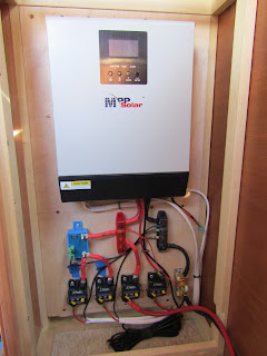
- 120V AC inverter - The MPP Solar "all-in-one" (AIO) converts battery 12V DC into 120V AC that is routed to a few outlets (e.g. where the microwave is plugged in). Power output is limited to 1000W continuous.
- 120V AC shore - power supplied from an external source like a house or RV park. This is wired to the MPP Solar "all-in-one" and when shore power is available (ie the trailer is plugged into an external 120V source) it is used to run the battery charger and also will bypass the 120V AC inverter to provide power wherever the inverter would have provided power. The refridgerator has a feature where it will automatically switch from 12V DC to 120V AC power when it's available.
12V DC Power
The 12V DC system runs off a 200 amp-hour lithium iron phosphate (LiFePo or LFP) battery. Nearly everything in the trailer that you'd normally use is powered by 12V DC. The exceptions are the microwave that requires 120V AC and the 120V AC outlets (the ones that look like typical outlets in your house). The 12V DC system can be charged by the solar panel or the battery charger built into the MPP Solar AIO.
Both the solar system and LiFePo battery are covered in other posts.
Batteries, particularly AGM-type, can be damaged if they are run down too far. The battery is protected from over discharging by a Victron battery protect device. It will automatically cut off DC power to most devices if the battery capacity drops too low. In addition to the automatic function, there is a "master" DC power switch that provide a single central place to turn off DC power. This switch is located to the left of the sink along with a switch for the water pump and inverter.

There are several DC breakers co-located with the MPP Solar AIO in a cabinet next to the dinette. The breakers are a resettable switch type that can be used to disconnect power if needed. The breakers are:
- 100 amp - main battery input to a terminal block for the 12V DC system
- 40 amp - power from the solar panel to the MPP Solar AIO - note the voltage on this line varies based on what the solar panel is generating
- 2x20 amp - power from the battery to the burb and street-side 12V DC fuze blocks


There are two 12V DC fuze blocks that distribute 12V DC power throughout the trailer. They are located in the tall cabinets on the curb and street sides of the Boles.

120V AC Inverter Power
The MPP Solar AIO includes a 1000W pure sine wave DC to AC inverter so that typical household appliances (such as a microwave) can be used. A 120V AC line runs from the MPP Solar AIO to a small breaker panel in the streetside tall cabinet. This breaker panel has a 15A input breaker and a tandem 15A output breaker. One of the tandem pair is spare, the other is wired to three outlets: 1) in the dinette end of the wall cabinet above the kitchen area; 2) to the microwave; and 3) to an outlet inside the curbside tall cabinet.
These outlets are actually wired with one plug receptacle for inverter power and one for shore power. They are marked on the outlet plate so you know which is which.
The inverter is only 1000W which is quite small. It's enough to run a small microwave (the one installed is 700W) or something like a blow drier on a low setting. You really need to be selective about what you might plug in as the total maximum amperage for the system is about 8.3 amps (1000W/12V). It'll surge higher can't support the continuous use.
The MPP Solar AIO inverter is not very efficient so the inverter function is wired to and ON/OFF switch located to the left of the sink next to the DC master switch and the pump power switch. This switch should be OFF unless you're using inverter power, or hooked up to shore power.
120V AC Shore Power
There is a 30 amp 120V AC inlet on the street side of the Boles that you can connect to a "shore power" source. Typically this will be either the house or an RV park source.
The shore power inlet runs to a small breaker box in the streetside tall cabinet. There are two 120V AC breaker boxes located in the back of the cabinet. The upper one is for inverter power and the lower one is for shore power.
The shore power input runs into a 30A breaker. From there it runs to a 20A tandem breaker. One leg of this breaker goes to several outlets including the one supplying 120V AC power to the refridgerator. As mentioned elsewhere, the fridge will automatically switch to using AC power when it's available.
Note: I needed a dual shore/inverter 120V AC system because I couldn't have the fridge switch to 120V AC power every time the inverter was switched on to microwave something. There would be large efficiency losses and the battery would drain much more quickly. This was a principle driver for the dual 120V system.
The outlets are all intentionally wired for 20A, even the inverter outlets. The inverter doesn't have the capacity so those outlets can't supply it, but the shore power can. My thought was that a future AC unit might be installed so I wired with 12AWG wire so that it could handle 20A.
The other half of the tandem output break is wired to the MPP Solar AIO. This provides power to the battery charger and, if selected, will bypass the inverter and power the inverter outlets as well.
Grounding
Grounding the system properly was a big concern and I researched it thoroughly. I followed the recommended procedure of running a large bare copper ground wire (8 AWG) from the 120V AC breaker panels to the trailer frame. The 120V AC shore inlet is connected to the ground in the breaker panel, so in effect it's also wired to this same ground plane. Here's my understanding of the rationale for this approach:
- If there is a short when the trailer is not connected to shore power then the frame becomes the ground plan and electricity will flow most easily there. Because a human in the trailer would be at the same potential, electricity would not flow through the human.
- If the trailer is connected to shore power then the ground connection would flow back through the shore power cable to the earth ground.
Closing Thoughts
The wiring was pretty straight forward but messy and there was a tone of wiring (ie $). This is no different than in a home but it seems there's got to be a more efficient way to do it. I'm going to have to think on that a bit before I tackle my next project.

What would I do differently next time? Here's some thoughts:
- I'd plan better. There were places I wished I'd run wires in the walls vs through the cabinets.
- I'd try to simplify the wiring design.
- I'd use lighter gauge wire for runs to low amperage devices from the fuze block. I typically used 14awg which is serious overkill for a 1 amp device.
- I'd consider separate components vs the all-in-one device. I like the AIO and there are incredible benefits but I worry about failures.
- I might consider going to 24V DC (but there are significant trade-offs that need to be considered).


Comments
Post a Comment